MCCB and Fuse — the Panel's Two Protectors
From here you're in the main-circuit (주회로) parts block. We'll trace the path electricity takes from the panel inlet down to the motor, one part at a time. First up: the two protectors guarding the panel entrance — the MCCB (molded-case circuit breaker) and the fuse. The L1 brown · L2 black · L3 gray · PE green-yellow conductors from Sequence control basics enter the panel together, but only L1/L2/L3 pass through the MCCB. PE connects to the protective-earth terminal and exposed conductive parts; it must not pass through the breaker or fuse.
MCCB — the main breaker that protects the whole panel


- Trip behavior depends on current, duration and the breaker’s time-current characteristic. Exceeding the rated current does not imply an immediate trip.
- A tripped breaker can be reset only after the fault is addressed and the manufacturer’s reset procedure is followed. The example places it at the panel inlet.
- Top three pins (1·2·3) = input (L1·L2·L3); bottom three (4·5·6) = output. They pair by column (1-4 · 2-5 · 3-6) — one circuit per phase.
Fuse — the single-use protector you replace once it blows
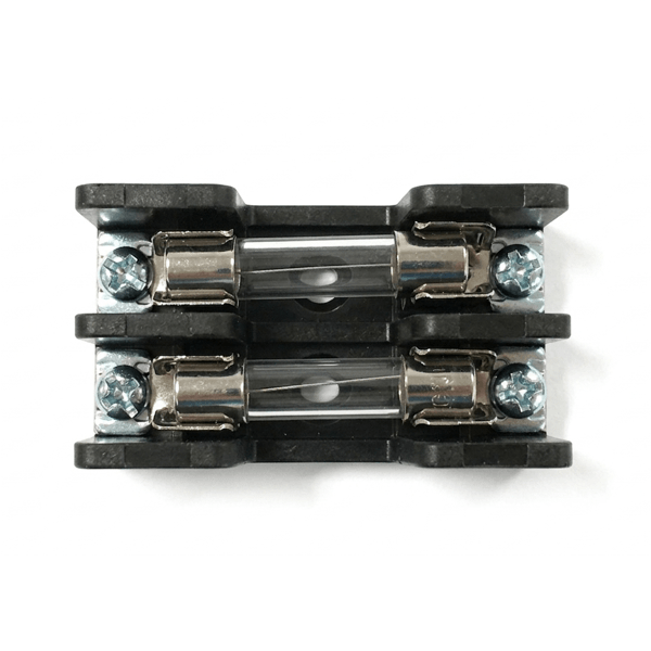
A fuse does the same job as an MCCB but with a different mechanism. When current and duration satisfy its operating characteristic, the element melts open — and once blown, that fuse is dead. The operator swaps in a new cartridge.
So why fit both a breaker *and* a fuse? They protect different things.
- MCCB → main circuit (heavy current) — guards the motor-side path against major faults.
- Fuse → control circuit (light current) — protects small loads like relay coils, buttons, and lamps in their own branch.
And a blown fuse leaves a clear physical trace that *something went wrong*, forcing the operator to investigate before reapplying power.
Main circuit vs control circuit — the color changes at the fuse
The conductors entering the fuse are brown (L1) and gray (L3), but the ones leaving it are yellow. In this example, the yellow conductors belong to the protected control branch. A fuse does not itself determine a conductor’s function or color; follow the circuit and the cited task instructions.
The full color and terminal rules are in Wire color & terminal rules.
Next
The part below the breaker that actually switches the motor on and off is next — the MC (magnetic contactor). It's the 8-pin relay's "coil flips the contacts" principle, just sized up for motor current.
Try it yourself
Open the practical project list →
Check your understanding
Question: Does a stopped motor prove the fuse input is de-energized?
Answer: No. Its supply can branch before the MC main contacts. Stopping a motor is not supply isolation.
Practice path and references
The practical project list may require sign-in. Create a project, choose a task and place the relevant components, then compare the contact/wiring paths explained here. The link does not preload a specific completed circuit.
Reference: Q-Net public-problem notice, 2025-08-04 edition, problem 14 pages 11-1 to 11-4 (work/wiring instructions) and 11-9 (component diagrams). Read the original for each task and any amendments. Site examples are distinct from general installation design requirements.
Trace a failure without guessing
If neither relay nor lamp responds but the main supply path exists, compare the control branch before blaming the motor. In the diagram, trace L1 → fuse → control contacts → coil → fused return → L3. One open segment interrupts the complete path. A motor can be stopped while parts of this branch remain supplied; a simulated OFF state is not a hardware isolation check.
Manufacturer background: Schneider Electric: thermal-magnetic trip operation. This explains why trip time depends on current; select actual protection from the specific device data and installation design.