Korean Electrician Conduit Finishing — Pipe, Saddles, and Pulling Wires
Once the wiring *inside* the panel is done, one job remains — connecting the world outside the panel (the supply, motors, water tank, and the control boxes that hold the buttons and lamps) with cable and conduit. This conduit work is graded separately: not whether the circuit is correct, but whether the pipework meets spec. The ±30 mm tolerance for off-panel parts was covered in panel layout — here we cover the pipe, saddles, and wire-pulling that join them.

The order — boxes first, wires last
Conduit work follows a fixed sequence.
- Place the boxes — octagon JB + control boxes.
- Conduit + terminal blocks + saddles — run pipe between the boxes, set the TBs at the pipe ends, clamp with saddles.
- Power cable — bring the external supply to the panel's input TB.
- Pull the wires — route them through the conduit you laid.
Just like the real job, you set the boxes first and run pipe between them (the trade order: chalk line → box → conduit). Wires go in last, after every pathway exists.
Two kinds of box — octagon JB and control box

- Octagon junction box (JB) — where several conduit runs meet and branch. It's the only legal branch point in a conduit run, so it must sit wherever pipe splits.
- 2-gang control box — an empty enclosure that holds buttons and lamps (electrically just a pass-through box), with ports top and bottom for conduit. A problem typically uses four of them; you seat PB (push buttons), RL·GL·YL (lamps), BZ (buzzer), SS (selector) into the slots — two per box, with the selector taking a slot on its own.
Two kinds of pipe — PE pipe on straights, CD conduit on bends
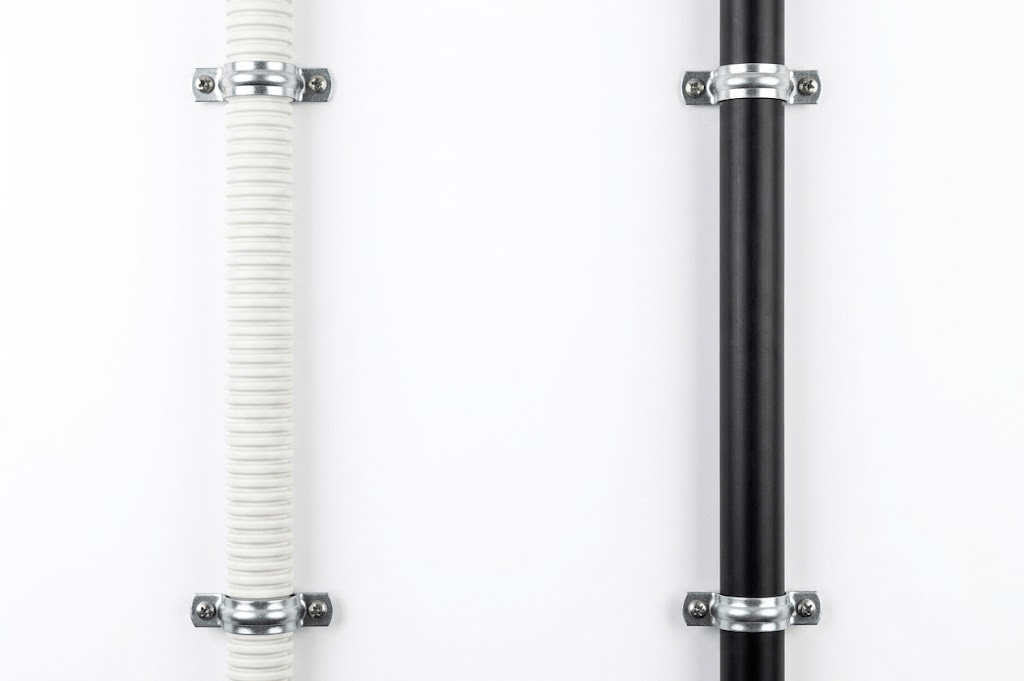
- PE pipe (black, rigid) — straight runs.
- CD conduit (white, flexible) — bends.
Each run has a specified type you must respect. Swapping a flexible run for rigid, or a bend for rigid pipe, is a points/disqualification matter.
Saddles — two rules for clamping the conduit
Once the pipe is laid, set the terminal blocks (TB) at the pipe ends first — saddle spacing is keyed off the TB position, so the TB goes down before the saddles. Then clamp the pipe with saddles.


- Rule 1 — near the panel edge, control boxes, bends (corners), and the octagon JB: saddle at the dimensions the diagram shows.
- Rule 2 — flank each terminal block (TB) with saddles 50 mm out on each side.
The power cable — one 4-core run

Pull one 4-core cable from the POWER source just off the top of the panel into the input TB (L1·L2·L3·PE). One jacket carries all four conductors (L1 brown · L2 black · L3 gray · PE green). Fasten it with two cable saddles.
Pulling the wires — routing conductors through the conduit
With the pathways laid, connect the panel terminals to the field devices, routing each wire through the conduit. Colors are unchanged — main circuit L1 brown · L2 black · L3 gray · PE green, control circuit yellow (wiring rules).
- Selector (SS) — three contacts. The common is SS, branching to A (Auto) and M (Manual). Turning the switch ties the common to A or M, picking the auto / manual circuit.
- Buzzer (BZ) — wires exactly like a lamp: a single control-circuit conductor.
Common mistakes — disqualification points
- Swapping a run's pipe type — keep PE pipe / CD conduit matched to straight vs bend.
- Skipping the octagon JB at a branch — every place pipe splits must go through the JB.
- Ignoring saddle spacing — the 50 mm flanking each TB is the easiest to miss.
- Wiring the cable straight into POWER — the cable must land on the input TB.
Try it yourself
Start from a blank board and take one problem all the way through — place the parts, wire the main circuit, wire the control circuit, then finish the conduit and pull the wires. Do that once and the whole practical clicks into place.