Korean Electrician Public Problem 14 — Control Circuit (Automatic Forward/Reverse)
The 22 main-circuit conductors already built the path power takes. Yet applying power does nothing, because MC1·MC2's coils aren't energized yet. The circuit that decides *when* to energize them — the control circuit — is this guide's whole subject. Its backbone is a single self-hold latch, with 8-pin relays, timers, and limit switches layered on as conditions.
The operation sequence — what the circuit must do
- Press PB1 → MC1 in — motor runs forward.
- Reach end-of-travel → after a delay, MC2 in — reverse (a timer makes the delay).
- Reach the opposite end → after a delay, MC1 in again — forward.
- Press PB0 → all coils drop — stop.
- EOCR trips → YL alarm lights + all coils drop — overload protection.

Read it as three paths
The 40 control wires are clearest split into the schematic's top, bottom, and middle paths.


- Top path — the L1 supply. The protected control supply runs through 9 terminals in turn, all joined into one node. Every coil's and timer's input side hangs off this single node. Wire it keeping each terminal within the 2-wire cap.
- Bottom path — the N return. The fuse output, EOCR's N-side b-contact, every coil's A2 (pin 12), and the timer commons all gather into a second node. Routing order is free — all that matters is the 10 contacts land in one node.

- Middle path — the logic. Between the two rails sits the part that produces the actual behavior: self-hold a-contacts, timer start signals and timed outputs, MC coil drive, the interlock, and the indicator lamps — scattered across several small nodes. For each node, route however you like, as long as its contacts end up joined into one node.
This problem's new part — the limit switch (LS)
The heart of automatic forward/reverse is detecting when the motor reaches end-of-travel — the job of the limit switch. There are two, one at each end of travel (LS1·LS2).
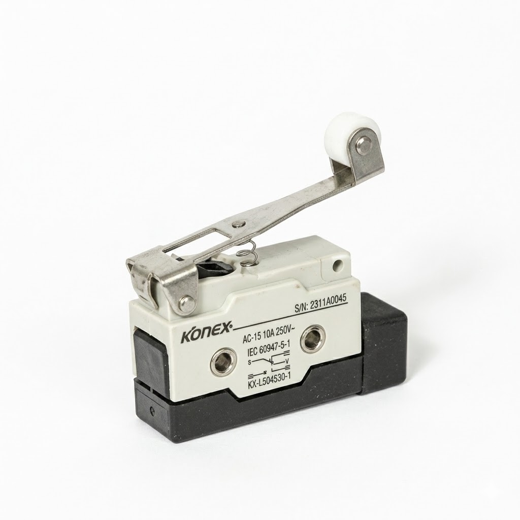
Each LS is a single SPDT (COM·NO·NC). That one pair does two jobs at once in the forward/reverse swap:
- NC (b-contact) — closed at rest, opens at end-of-travel. → Wired into the top path (L1 supply), so reaching the end cuts that side's coil supply.
- NO (a-contact) — open at rest, closes at end-of-travel. → Wired into the middle path's self-hold input, so reaching the end triggers the opposite direction.
So one trip of an LS does both at once: kills this side's motor AND starts the other side's — that's the whole automatic forward/reverse mechanism.
The interlock — skip it and you get a 3-phase short (disqualification)
Next
Having followed one forward/reverse problem from parts to layout to control, look at a complete problem of a different shape — Public Problem 1, fully analyzed.
Try it yourself
Wire Problem 14's control circuit and drive it with the PBs and LSs in the simulator →