What Is a Timer (T) Relay? Coil (2·7) and Timed Contact (8·6·5)
A timer belongs to the same relay family as the 8-pin relay and the EOCR — "coil energizes, contacts flip." The one difference is when they flip: not the instant the coil energizes, but after a delay you set in advance. The Korean term is 한시(限時) 동작 — "time-limited" operation.
Coil (2 · 7) — the terminals in this model
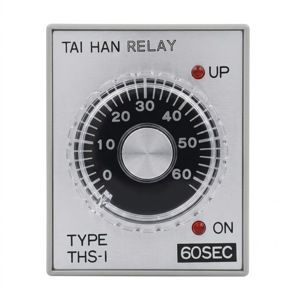

- 2 · 7 (coil) — put a voltage across these two and the timer energizes; the internal count starts at that instant.
- The moment the coil drops — the count resets to zero immediately and the contacts snap back to rest (instantaneous return). Break and re-energize and the count starts over from zero.
This example uses the exam socket convention. Before substituting actual devices, verify supply ratings and the function of every pin.
Timed contact (8 COM · 6 timed-NO · 5 timed-NC) — flips only after the delay

- 8 (COM) — the timed contact's common pole; one leg of the fused supply usually lands here.
- 6 (timed-NO / delayed-ON) — open at rest and during the count, closes when the delay expires. The pin behind "turn this on N seconds after pressing."
- 5 (timed-NC / delayed-OFF) — closed at rest and during the count, opens when the delay expires. The pin behind "keep on for N seconds, then cut automatically."
Both share one common (pin 8) — the same "one coil moves the whole set together" pattern as the relay.
See it work
This illustrated example's timer is set to 3 seconds.


Press PB1 and the coil (2·7) energizes immediately, but the motor and GL stay dark — pin 6 is still open, so current can't reach the MC coil behind it. The instant 3 s elapses, 8-6 closes, the MC coil energizes, the motor spins, and GL lights.
This page describes a non-retentive on-delay example. Use the timing chart and device manual to distinguish off-delay and other modes.
Next
That completes the tour of every core part that goes into the panel. Next come the rules of *placing* those parts on the board without getting disqualified — see Control-panel layout.
Try it yourself
Open the practical project list →
Check your understanding
Question: If a three-second on-delay loses coil power after two seconds, does it resume with one second left?
Answer: This non-retentive model restarts its count. Check the actual device mode and reset specification.
Practice path and references
The practical project list may require sign-in. Create a project, choose a task and place the relevant components, then compare the contact/wiring paths explained here. The link does not preload a specific completed circuit.
Reference: Q-Net public-problem notice, 2025-08-04 edition, problem 14 pages 11-1 to 11-4 (work/wiring instructions) and 11-9 (component diagrams). Read the original for each task and any amendments. Site examples are distinct from general installation design requirements.
Compare an interrupted timing cycle
For the illustrated non-retentive three-second timer: hold PB1 for two seconds, release it, then hold it for two seconds again. The timed NO contact remains open: separate attempts do not add up to four seconds. Holding it continuously for three seconds closes 8-6. The instantaneous contact, if provided and connected, follows a different timing rule.
OMRON’s timer overview explains the distinction between timing modes. Check the exact product’s timing chart before treating a reset or output behavior as universal.